Saturday, October 1, 2016

Post 5: The Lake Washington Ship Canal Bridges, Salmon Bay

With the housekeeping of the three major bridge types out of the way, let's take a tour of the Lake Washington Ship Canal over the next couple of days. This will allow us to explore a new bridge type, bascule bridges, Coast Guard regulations, and my photo collection of these 5 movable bridges. The first bridge on the list? Salmon Bay.


BNSF Railroad Bridge Number 4.

This bridge is the first bridge to greet a mariner on the Lake Washington Ship Canal and is an offshoot of the bascule bridge type we have previously discussed. A Heel-Trunnion bridge, this name derives from the trunnion being located in the heel of the bridge, (If you consider the bridge to look like a large foot) often above the roadbed by a small amount. These Bridges are fascinating and at first glance a little difficult to understand, so let's break down the parts and pieces.
The bridge has 5 joints that pivot during the lift sequence. The drawspan will revolve around the trunnion as with a regular bascule bridge, but the counterweight has been moved away from the drawspan itself. The operating strut in this image would slide to the left, and pull on the top-left corner of the drawspan. The counterweight and its associated frame on top of the triangular base would rotate down and fold the bridge as seen below:

The heel trunnion design seems useful for a situation in which it is not desirable to construct a large below-grade counterweight pit, simply because the counterweight pit is eliminated from the design. This bridge and another over the Duwarmash River in Seattle are both railroad bridges and are in places where a large counterweight pit would be difficult to build. I wish I knew more about why this design is used in place of regular bascule bridges, since it seems like the underground counterweight is too little of an issue for a bridge. I'd bet this design is also more stable since the closed drawspan's trunnion is not a long distance away from the live-loads of traffic. 

This bridge stands sentinel outside the Ballard Locks, or Hiram M. Chittenden  Locks on the entrance to the Lake Washington Ship Canal. It is usually maintained in a partially open position, except when closed to allow trains to pass over it. I have seen for myself and spoken to a tugboat captain who regularly requires a full opening, where the drawspan is nearly vertical. 

There is no good way to get close to the bridge for sightseeing purposes but the locks provide a decent vantage themselves, as does a bike path under the railroad line from which the first picture was taken. 

Now that all three bridge-types have been introduced, the next post will focus on the next bridge in the Seattle Sequence; Ballard
 

Thursday, July 14, 2016

Post 4: The Swing Bridge

The Swing Bridge: this is WA-529NB over Steamboat Slough
The last of the three primary movable bridge types is the Swing Bridge, which opens on a pivot to clear the channel. The pivot can be either in the center of the movable span, or offset from it with a counterweight. In common form, this pivot usually takes the form of a large concrete cylinder utilizing a rack and pinion arrangement for gearing the bridge open. This cylinder sits in the channel and when the bridge is open must necessarily take the weight of the entire span. (Again we see a trend with movable bridges, when open all of their weight is usually concentrated on a small area: the swing bridge pivot, the bascule trunnion and the lift bridge counterweight ropes.) The drive motors are located to my knowledge either in the pivot mechanism or in a machinery house above the bridge. When opening, mechanical wedges first retract to allow the bridge to pivot, and then the motors drive a shaft down through the road deck to the rack and pinion and bearing. There are two different primary bearing types, ring and center, but I do not recall any particulars of the two. I think it may be more appropriate to break into a couple pictures to round out this post, and better demonstrate what I am talking about.

The drive mechanism of a swing bridge


Included to show an elevation of the joint with the fixed span
Swing bridges are something of an older type and many movable bridge authorities would tell you that they are obsolete. The biggest drawback of the swing bridge? It basically halves the channel for vessels with the big concrete obstacle in the way:
Swing Bridge in the open position

 In my personal experience, they are also often painfully slow. At the same time I think they are also some of the prettier of the movable bridges; they actually look like a normal bridge for the most part (Wait for heel-trunnion bridges to see what I mean) and are getting harder to find in the modern day. Lots of swing bridges have entered what I call "Once Upon a Swing Bridge" status, permanently closed or open and rusting away.  Often times, the swing span is even replaced by something else, like a vertical lift span as seen here:


The silver swing span is in my opinion more elegant, but the brutal functionality of the lift span has won out in this case. Having a channel which is twice as wide certainly doesn't hurt either, and since the days of commercial sail are long behind us, a wider channel with a limited maximum clearance is far more valuable than a narrow unlimited one. Barges tend to be wide and flat, not narrow and tall, perfectly unsuited to the traditional swing bridge. That's not to say they don't have their use and place, they'll continue to silently revolve.


Sunday, July 3, 2016

Post 3: The Vertical Lift Bridge

Hello again bridge enthusiasts!

I'm sorry that it has taken so long for me to post. I thought that my plan for a post on bascule bridge drive systems would be best served by a few pictures I haven't yet taken of some drive gears on display, so I thought instead I would move on to a different type of bridge altogether, (vertical lift) and post about bascule drive some other day.

I am having difficulty opening this overview on the type. The Vertical Lift bridge is one in which the deck lifts vertically upward away from the river, increasing the clearance beneath it. Of the three basic types of movable bridge, it is unique in that it never allows infinite clearance vertically for vessel traffic. Pioneered in the early 20th Century by Waddel, let's have a quick look at a few examples of the type:


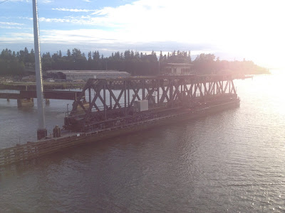
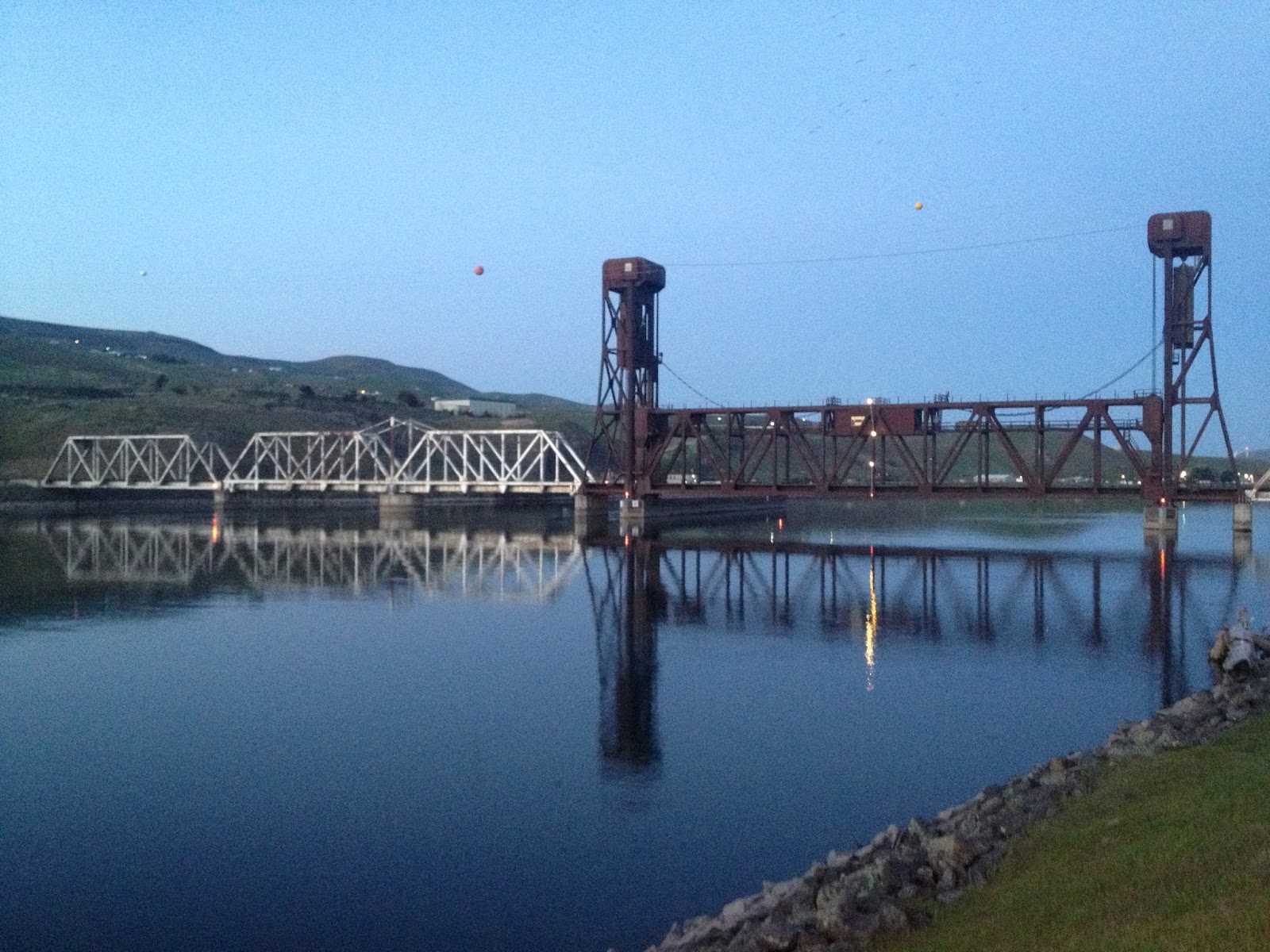
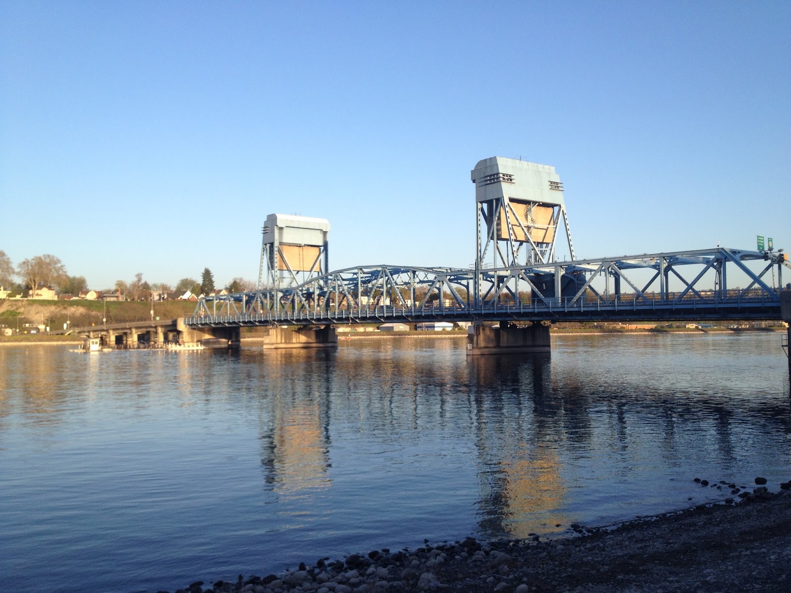
We'll use this railroad bridge over the Clearwater River in Idaho as our typical vertical lift bridge. 

Immediately one ought to notice the towers, which serve as a support and guide-way for the lift span when the bridge is being raised. The bridge itself is pulled by a combination of drive ropes and  counterweight ropes  which are steel cables (chains are also possible) running over counterweight sheaves (pulleys) located in the tops of the towers. When actuated, the drive ropes pull on the lift span at each of the four corners and raise it straight up. As the deck goes up, the counterweight goes down, and the ropes pass over the sheaves, shifting the balance-point of the bridge from span heavy to weight-heavy. (These are two very important concepts in and of themselves and will be discussed in a later post). To close, the process is reversed and the bridge is lowered back down. As with bascule bridges, there is usually some sort of mechanical lock to prevent the possibility of the bridge coming open inadvertently. 

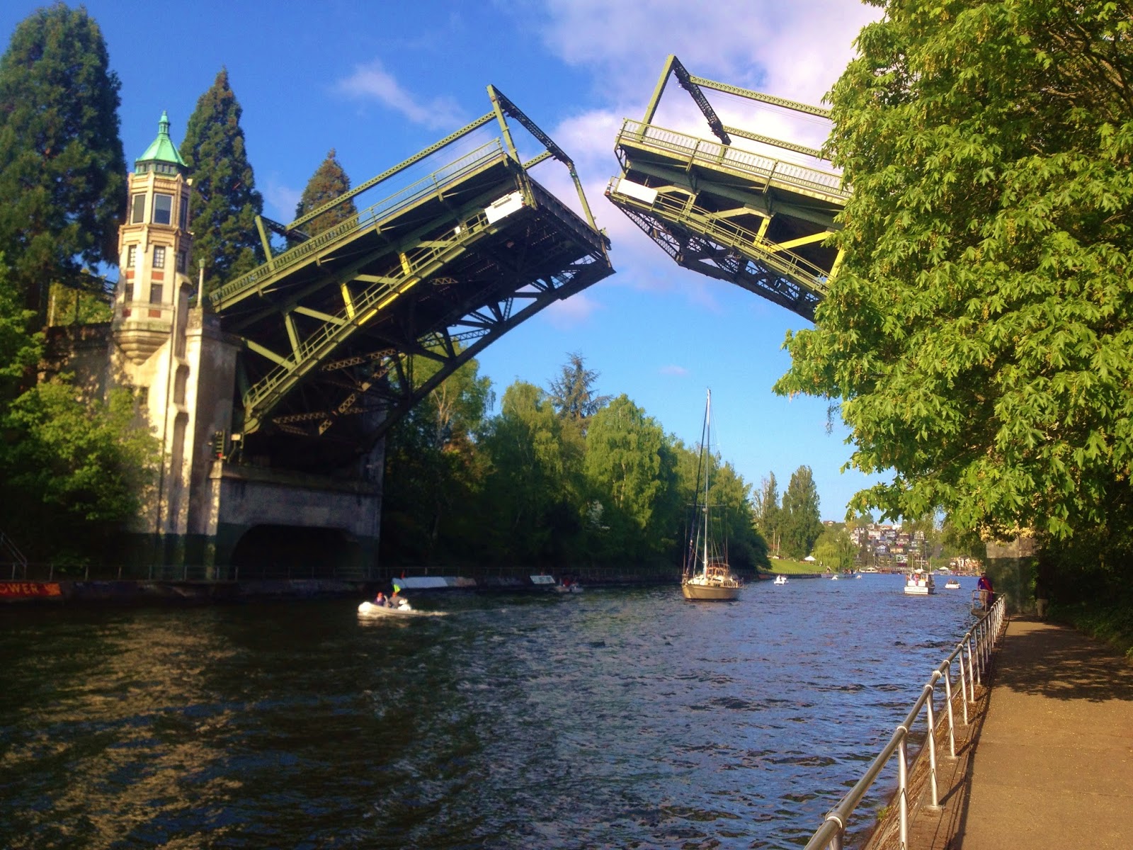
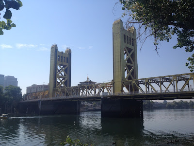
Tower Bridge; Sacramento, California
The vertical lift bridge is in my opinion a very interesting type. I like them. Their structure is on full display. It is notable that the Coast Guard loves these things. Their mechanism is not housed in some counterweight pit or pivot pier, and they are usually the largest examples of movable bridge. This is because at all times, the bridge is being supported at the four corners and never changes orientation or support. Bascule bridges must of course rotate to vertical, and swing bridges swap compression and tension between their top and bottom chords. (Or do they? Correct me on this if you know better). There are two drive types for these bridges, span drive, where the motors and gearing are located in a house on the lift span, and these pull up both sides of the bridge, and also tower drive, which use a pair of motors and gear drives in each tower to pull up each end of the bridge. Tower drive bridges have the problem of synchronizing both ends, span drive bridges have to keep track of long drive ropes as they twist around the towers and span. I will at some point include a diagram of this.

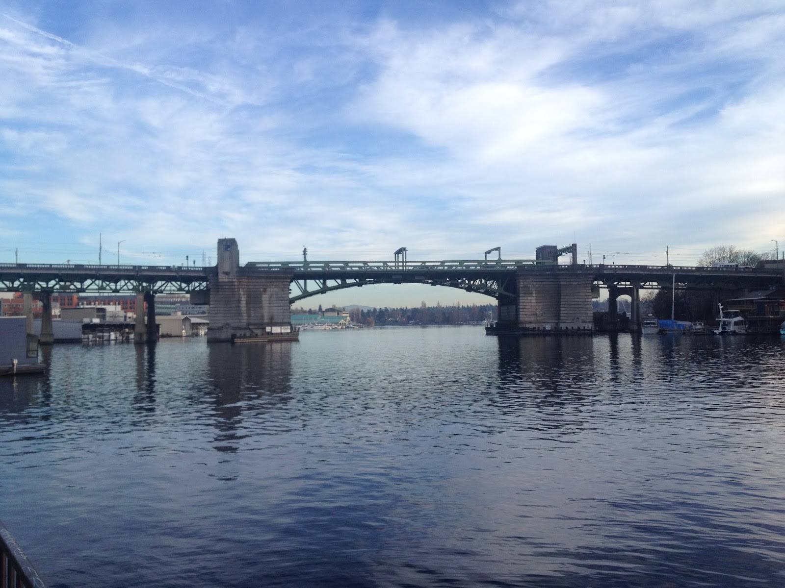
There are a few distinct drawbacks to the vertical lift span, however. As alluded to above, the channel is never fully unrestricted; there is still a maximum height on the vessels that may pass through it. The towers can be ugly or block sight-lines, and are often prone to being wiggled out of alignment (My Grandfather relates stories of the Hawthorne Bridge in Portland, Oregon). Additionally, the amount of bridge that has to be built to have utility is quite great. Speaking solely of western US navigable waterways, a vertical lift bridge sometimes does not make sense, simply because the complexities of building towers and adding counterweights to still limit maximum channel clearance does not make sense. Vertical lift bridges are in my opinion simply uneconomical for small sloughs and waterways where traffic is usually sailboats and not motor vessels. Europeans see things a little differently, but their vertical lift bridges are different too. (I don't have photos at this time, however).

Perhaps I just like vertical lift bridges because Seattle is the domain of the Bascule Bridge and I just need some variety. Regardless, I think the next post will complete the triumvirate of movable bridges, with the swing-bridge, and I hope you will enjoy it. Im sorry that this post wasn't as technically detailed as the last one, but fun nonetheless. See you soon!

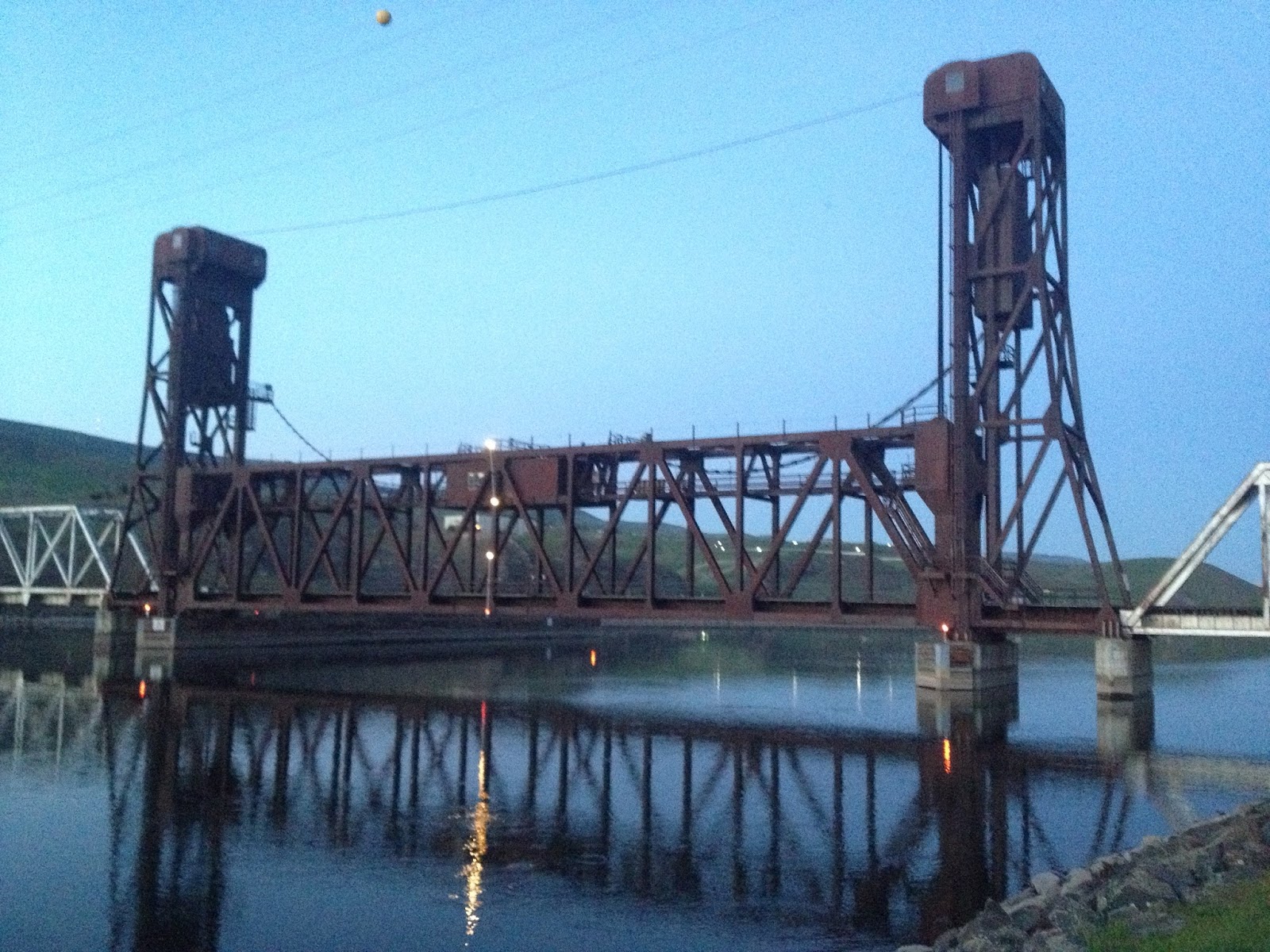
Snake River Bridge, US 12 in Idaho

Friday, June 24, 2016

Post 2: The Trunnion Bascule Bridge


The Trunnion Bascule Bridge, which exists in both single and dual-leaf forms, is probably the most generic and well known type of movable bridge. 'Bascule' comes from the French for 'Balance' and indeed that is what this design is all about. A large piece of concrete or some other counterweight is used to offset the weight of the span. To open, the span rotates on a trunnion, and as the counterweight goes down, the bridge goes up.

Let's see if we can't have a closer look at the parts of the bridge and how this works:


Sorry, I just love playing in AutoCAD. Anyway, we can see the center of rotation is the Trunnion, which in real life varies in diameter but can approach 2 feet, upon which the entire rotation is based. The trunnion is precisely machined (often of bronze) and is effectively a very large bearing. The large diameter is required because during rotation, the entire weight of the span and counterweight are more or less concentrated on it. The Counterweight, which is shown here as sort of a polygonal shape with diagonal stripes, is made of concrete and depending on density requirements can often include metal inserts for added weight. The last features of note here are the Live Load Shoes, which, when the bridge is closed, serve to carry the live loads of vehicle traffic instead of having them concentrate on the trunnion. 

For simplicity's sake, I drew a typical single-leaf bridge. In bascule bridge terminology, a 'leaf' is simply the bridge deck, i.e. the moving part. There can be single- or dual-leaf designs. In the case of dual-leaf, instead of a live-load shoe at the 'toe' of the bridge leaf, there is a another bridge leaf. In order to limit relative vertical deflection between the bridge leafs at the joint, Span Locks are used. The most common span lock system is a linear prong which extends from one side of the joint to the other and slides into a receiver there.  (A similar arrangement also secures a single-leaf bridge to its footing.) On the Lake Washington Ship Canal's four trunnion bascule bridges, these span locks are audible from the shore, and on the Montlake bridge especially, somewhat visible, particularly the flywheel of the span lock motor. The next time you walk on one of these bridges, look down through the joint on either side and try to find the span locks. They should be the only thing that bridges the gap from one side to the other. 

Below are a couple of photos which should clarify the live load shoes.  The bridge is the Fremont Bridge on the LWSC in Seattle, Washington, and is one of the busiest movable bridges in the United States.
Overview from near-elevation at about 1/3 full open


Here we see the live load shoe and contact plate in both the open and near-closed position. As is plainly seen, the bridge rotates down and settles into position in the saddle shown. Keep in mind the massive scale of the components here, the railing is 3ft high or so, and as such the shoe and plate are probably around 18 inches square.

I know we covered a lot in this post and even still have not mentioned how these bridges are pulled open and shut. Next time we will look to Alameda, California and the Park Street Bridge which illustrates the gear system quite well. I may also take some pictures of the drive system on display at the South Park Bridge in Seattle, to exemplify the motors and gearing involved. Until then, see you soon!


Saturday, June 18, 2016

Welcome/Post number 1

Hello drawbridge enthusiasts and/or those with curiosity about drawbridges! 

Welcome to a blog which I hope to craft into a decent mode of passing on the things I have learned about my fascination with drawbridges!

First, a bit about me. I am a 20 year old Civil Engineering student at the University of Washington in beautiful Seattle, Washington, where I have the pleasure of exploring the 9-½ drawbridges located here, in addition to some a little farther out. (What is 'Half' a drawbridge? We'll get to that.) Anyway my current goal in Engineering School is to go on to become a drawbridge engineer. My fantasy goal is to become the preeminent movable bridge engineer in the world, who becomes the international authority on the topic and whom municipalities all over the world come to for advice and consulting. It's a big fish idea, but thankfully, movable bridges are a small pond in the world. It is a very niche market, but I hope to make my mark.

Anyway the first couple of posts are going to give a brief overview of drawbridges and the history, types and functions of the drawbridges in the world, and then continue on to photos of specific examples. Enjoy!

Post 1: The Movable Bridge
 
Salmon Bay Bridge in Seattle, Wa.

A movable bridge, as implied by name, is a bridge which can be moved, nowadays usually with the primary goal of affording more channel space to vessels than could be provided with a fixed span bridge. When we hear the term drawbridge, we often think of castles and moats, and indeed early movable bridges were of that type, deployed for defense over moats. It was not until industrialization, however, that movable bridges began to take the forms we know today. Certainly they existed in wooden forms. Vincent Van Gogh was familiar with them as his paintings show, but it wasn't until the advent of steel as a building material that large spans could be crossed (However, large wooden swing spans did exist).

Anyway the movable bridge evolved into three main types, each with various subtypes to go along, as well as minor types. The three basic bridges are:

The Swing Bridge: Rotate the bridge in a horizontal plane to clear the channel
The Vertical-Lift Bridge: Lift the bridge straight up out of the way of the vessel
The Bascule Bridge: Use a large weight to see-saw the bridge out of the way

With the wonders of autoCAD, I will now attempt to illustrate what is going on.


And here are physical examples of each:


Alright that does it for post 1, over the next couple of posts we will delve into the evolution of each type and the particulars. See you soon!